A Neural Network Based Teleoperation for Remote Controlled Vehicles
The authors propose and evaluate a unilateral vehicle teleoperation architecture combining wave variables for communication delay stability with an adaptive radial basis function network for...
1. Introduction: The Challenges of Direct Teleoperation
As autonomous vehicle architectures advance toward broader deployment, state regulatory frameworks across several U.S. jurisdictions explicitly mandate remote vehicle teleoperation as an essential human-in-the-loop safety fallback. Direct teleoperation grants a remote human operator continuous steering, throttle, and braking authority when onboard autonomous software encounters complex edge cases outside its operational design domain (ODD). However, exercising direct real-time control over commercial cellular networks introduces severe control-theoretic vulnerabilities. Researchers Ning Ding and Azim Eskandarian highlight that direct teleoperation is fundamental constrained by two concurrent bottlenecks: stochastic communication latency over public wireless networks and the remote operator’s physical inability to perceive unmodeled environmental disturbances—such as crosswinds, road bank angles, grade shifts, and highly nonlinear tire-road dynamics.
Core Thesis: To maintain closed-loop stability across delay-prone wireless links without compromising real-time execution, the authors propose a dual-layer control architecture combining a unilateral Wave Variable (WV) transmission framework with a single-layer Radial Basis Function Network (RBFN). The WV framework passively guarantees stability under stochastic network delays without reflecting disruptive force feedback to the operator, while the RBFN actively estimates and cancels unmodeled dynamic disturbances online within strict edge-hardware compute budgets.
2. Dual-Layer Control Architecture: Wave Variables + Adaptive RBFN
The framework developed by Ding and Eskandarian addresses teleoperation instability by structurally decoupling delay-induced communication passivity from dynamic disturbance rejection on the vehicle side.
+------------------+         Wave Variable Channel         +--------------------+
| Remote Operator  | =====================================> |   Remote Vehicle   |
| Command Generator| <===================================== | State Feedback (v,)|
+------------------+   Forward Delay T1 / Backward Delay T2 +---------+----------+
                                                                      |
                                                                      v
                                                            +-------------------+
                                                            |   Adaptive RBFN   |
                                                            | Disturbance Cancel|
                                                            +-------------------+
2.1 Passive Signal Transmission via Unilateral Wave Variables
In traditional bilateral robotic teleoperation (e.g., surgical or industrial manipulators), Wave Variables (WV) passivate delay-prone communication channels by encoding force and velocity signals into wave vectors. However, directly applying bilateral formulations to ground vehicles is inappropriate: transmitting ground-reaction forces or steering-torque feedback back to the operator station injects high-frequency road vibrations and environmental disturbances directly into the operator’s interface.
The authors resolve this by formulating a vehicle-specific, unilateral Wave Variable architecture. Power-conjugate command and state pairs are defined across two independent transmission channels:
- Longitudinal Channel: Transmits command force and longitudinal velocity state , defined by .
- Lateral Channel: Transmits steering rate command and vehicle yaw angle state , defined by .
For each channel , command and state variables are encoded into wave variables and using tuned characteristic channel impedances :
Subject to time-varying forward delay and backward delay , wave transformations across the channel satisfy and , where subscript denotes the operator (leader) and denotes the remote vehicle (follower). Decoding these wave signals at the vehicle recovers command force and steering rate , while returning state feedback and to the human operator. This formulation guarantees channel passivity without reflecting external physical road forces back to the steering wheel.
2.2 Decoupled RBFN Dynamics and Real-Time Edge Adaptation
Because passive wave transmission preserves stability but cannot actively compensate for unmodeled physical forces (e.g., side gusts or road incline changes), an online adaptive Radial Basis Function Network (RBFN) operates directly on the vehicle’s embedded controller.
- Wave Variable Passivity: Passively absorbs stochastic network delays () without requiring an explicit mathematical delay model or predictor.
- RBFN Uncertainty Estimation: A single-layer Gaussian RBFN acts as a model-free online lumped uncertainty estimator. Single-layer networks are selected over deep multi-layer neural networks or model-predictive formulations (MPC/NMPC) to eliminate multi-layer backpropagation overhead and solver iteration delays.
To achieve strict real-time execution, the Gaussian basis functions use uniform center grids placed over an estimated operating envelope. Basis widths are derived via the neighbor-overlap parameterization rule: where represents the grid spacing and sets the neighbor-overlap parameter, ensuring basis functions decay to half peak value at adjacent grid centers.
To prevent computational cross-coupling across control axes, the 6-DOF composite error vector is decoupled into longitudinal tracking error and lateral/yaw tracking error . The Lyapunov-based weight adaptation laws execute independently on edge hardware without cross-coupling calculations: where are adaptation gains, are symmetric positive-definite matrices derived from Lyapunov equations, encapsulates vehicle mass, is the pseudo-inverse of the lateral control input matrix, and is the vector of Gaussian basis functions.
2.3 Stability Bound Summary
Ding and Eskandarian establish closed-loop stability using a composite Lyapunov storage function combining human operator passivity, wave-channel energy storage, and vehicle tracking error dynamics: The wave storage function explicitly captures power stored in the communication pipeline. Differentiating demonstrates that time-varying transmission delays enter the system differential equations strictly through integration bounds. Under bounded operator inputs ( and ), the composite Lyapunov derivative satisfies: This proves that composite tracking errors remain Uniformly Ultimately Bounded (UUB). The residual ultimate error bound is defined as: Because depends strictly on operator command bounds () and positive design gains (), the system’s ultimate stability envelope is proven to be independent of network delay durations and .
3. Simulation Benchmarks: Comparative Performance Trade-Offs
The proposed controller was evaluated in a high-fidelity MATLAB/Simulink environment utilizing a 3-DOF nonlinear vehicle dynamic model (incorporating longitudinal, lateral, and yaw motions alongside aerodynamic drag, rolling resistance, grade effects, and bank angles). All algorithms were evaluated under a strict sampling budget (), enforcing zero-order holds whenever controller execution time () exceeded . Stochastic wireless latency was generated using a Generalized Extreme Value (GEV) distribution fitted to empirical 4G network traces.
Execution Runtime Budget vs. Controller Execution Time (t_E)
20 ms Edge Budget Threshold |-----------------------------------|
NMPC Lateral (75.20 ms)    |===================================================> [OVERRUN]
NMPC Long. (44.38 ms)      |===============================> [OVERRUN]
MPC Lateral (2.58 ms)      |===>
LQR Lateral (0.12 ms)      |=
RBFN Proposed (0.03 ms)    |*
PID Long. (0.02 ms)        |*
The adaptive RBFN architecture was benchmarked against Proportional-Integral-Derivative (PID), Linear Quadratic Regulator (LQR), Model Predictive Control (MPC), and Nonlinear Model Predictive Control (NMPC) frameworks across severe environmental disturbances ( road slope, crosswinds, bank angle).
| Controller | Longitudinal (ms) | Lateral (ms) | Key Performance Metrics / Limitations Under Disturbances |
|---|---|---|---|
| RBFN (Proposed) | ~0.03 ms | ~0.03 ms | Fast recovery ( at ), ultra-low runtime, online adaptation. |
| PID | 0.01–0.02 ms | N/A | Lowest runtime, but severe settling degradation () under slope/wind. |
| LQR | N/A | ~0.11–0.12 ms | Low latency, satisfactory nominal tracking, lacks online disturbance adaptation. |
| MPC | 1.79–2.01 ms | 2.40–2.58 ms | Moderate compute, but degrades () when disturbances exceed internal model bounds. |
| NMPC | 39.56–44.38 ms | 72.40–75.20 ms | High model accuracy, but budget creates massive control overruns. |
Analysis of Simulation Trade-Offs
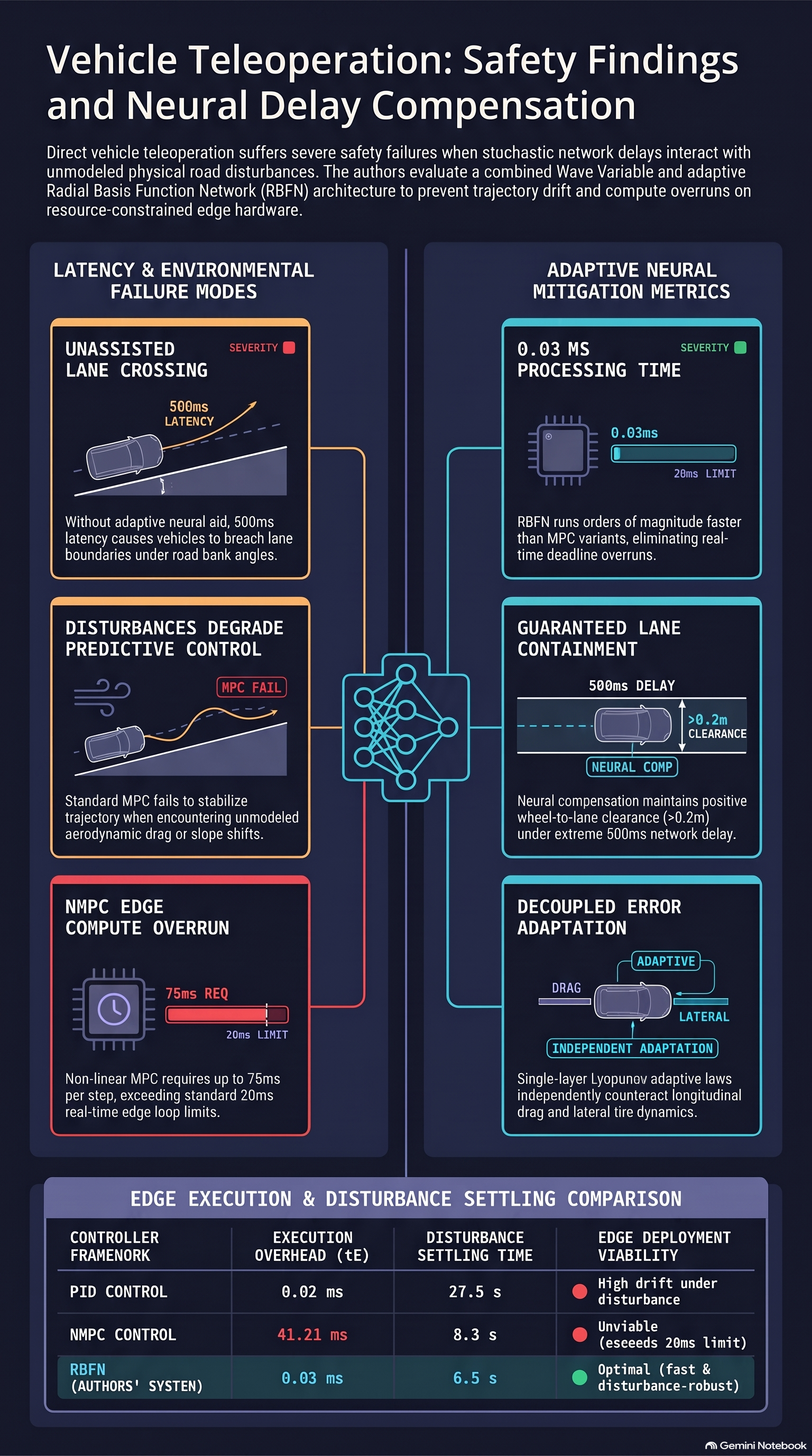
- Computational Efficiency & Edge Real-Time Compliance: The RBFN controller executes in approximately , matching the speed profile of basic PID () and LQR (). Conversely, NMPC requires for longitudinal control and for lateral control per step. On vehicle edge processors operating on a loop, NMPC triggers continuous actuator command holds, inducing lag and control degradation.
- Quantitative Recovery Under Severe Disturbances: In longitudinal evaluations at under an slope and wind gust, fixed-gain PID required to settle (peak speed error ) due to its inability to update internal dynamic parameters. Kinematic MPC required () as environmental inputs fell outside its predictive model horizon. The proposed adaptive RBFN compensated for unmodeled drag and grade online, recovering nominal speed in () while using less than of MPC’s compute time.
- Simulated Delay Sensitivity (Tables II & IV): Simulated forward delays were escalated from at . Under longitudinal slope/wind disturbances, RBFN peak speed deviations () degraded gracefully from (settling times rising from ). Under lateral bank disturbances, deviation () scaled mildly from ( increasing from ), demonstrating stability prior to hardware deployment.
- ISO 3888-1 Double Lane-Change Benchmarks: Evaluated under aggressive evasive double lane changes at and (Table V), RBFN limited lateral deviations to at , and at . RBFN outperformed LQR (), MPC (), and NMPC ().
4. Real-World Hardware-in-the-Loop (HIL) 4G Testing
To validate the theoretical architecture against real human operator dynamics and live cellular network behavior, Ding and Eskandarian performed hardware-in-the-loop (HIL) experiments on a wireless physical testbed.
4.1 Testbed & Delay Envelope
- Operator Control Station: Integrated a Logitech G29 gaming steering wheel and pedal set with a ROS2 (Foxy) node executing at a cycle time (). Onboard vehicle camera streams provided visual feedback.
- Physical Remote Vehicle: A 1/10th-scale test vehicle equipped with a Vedder Electronic Speed Controller (VESC) providing direct motor torque regulation.
- Cellular Network Pipeline: Evaluated over an active 4G network with measured default latencies of ~100 ms forward (operator-to-vehicle) and ~300 ms reverse (vehicle-to-operator). Latency stress tests emulated forward delays up to 500 ms.
4.2 Safety Failure Prevention (Lane Containment)
Physical experiments exposed critical safety limits during high-latency lateral maneuvers on banked surfaces ( slope). Safety boundaries were quantified by measuring distances from vehicle wheels to lane boundaries (), where negative values () indicate outer/inner wheel lane crossing failures.
- Unassisted Direct Control Breach: At forward velocity under delay on a banked road (Table VII), unassisted direct human teleoperation suffered complete loss of lane containment. The inner wheels breached the lane boundary, registering in laboratory and outdoor downhill tests, and in outdoor uphill tests.
- Assisted System Containment: With the proposed neural-wave controller active, the vehicle maintained positive inner-wheel safety margins across all elevated latency levels up to . At under delay, the system achieved positive margins of (laboratory), (outdoor uphill), and (outdoor downhill). The assisted controller maintained across all physical experimental configurations.
4.3 Trajectory Tracking
Empirical data collected across laboratory and outdoor environments ( crosswinds, uneven terrain) confirmed robust trajectory execution under latency stress:
- Target Speed Tracking Stability: As documented in Table VI, at latency and target speed outdoors, speed deviation without assistance reached ( error margin). The adaptive RBFN suppressed speed deviations to . Speed traces in Figure 2 show that while unassisted direct control overshot targets up to , the RBFN system maintained tight velocity tracking near .
- Closed-Track Speed Regulation: Experimental closed-track speed traces in Figure 3 ( vs. ) demonstrate smooth velocity tracking. In variable-speed trials (), the RBFN closely matched desired velocity generated by the Trajectory Design Module, whereas unassisted driving produced large velocity oscillations.
- Track Boundary Maintenance: Recorded closed-loop spatial trajectories in Figure 4 confirm that the Trajectory Design Module generates dynamically feasible reference states in real time. Steering execution remained centered within track boundaries during both idle-speed () and variable-speed () tests.
- Latency Robustness Limits: Closed-loop path trajectories in Figure 5 illustrate spatial paths under extended delays (). Even at network latency, the vehicle maintained stable path bounds without destabilizing oscillations.
5. Failure-First Research Takeaways & Conclusion
For robotics engineers, red-teamers, and AI safety researchers evaluating edge deployment constraints in safety-critical autonomous systems, this empirical paper highlights key systemic insights:
- Edge Compute Bottlenecks Can Exceed Network Latency Risks: Model-heavy non-linear predictive controllers (NMPC) introduce internal execution delays () that exceed real-time edge processing budgets (). This compute overrun induces actuator command holds that degrade vehicle controllability independently of network performance.
- Structural Decoupling Protects Against Stochastic Jitter: Separating passivity preservation (via Wave Variables) from online disturbance compensation (via single-layer RBFNs) provides a resilient safety architecture. Passive transmission channels handle network latency jitter, allowing lightweight neural networks to focus strictly on physical disturbance rejection.
- Online Neural Adaptation Prevents Physical Boundary Failures: Unassisted teleoperation degrades rapidly when latency is coupled with unmodeled environmental forces, leading to boundary breaches. Low-dimensional, single-layer neural adaptation prevents vehicle control loss during unmodeled friction or incline changes where fixed-gain controllers fail.
In conclusion, Ning Ding and Azim Eskandarian demonstrate that combining unilateral wave variable passivity with decoupled adaptive RBFNs resolves the dual challenges of network latency and dynamic environmental uncertainty in ground vehicle teleoperation. The authors note that future research will focus on extending theoretical stability proofs to coupled multi-input multi-output (MIMO) vehicle dynamics, developing dedicated passivity-preserving mechanisms for severe network packet loss, and validating the architecture on full-scale autonomous vehicle platforms.
Read the full paper on arXiv · PDF